In the previous insight, we explored the inner workings of a Log-Structured File System (LFS). In this insight, we will apply those concepts to explore a file system designed specifically for Solid State Drives (SSDs) - the most prevalent storage media in modern data centers.
This 2015 paper, authored by researchers at Samsung, Korea, was presented at the highly regarded USENIX File and Storage Technologies (FAST) conference and presents the design of a file system for SSDs. This paper is of particular interest for several reasons: it provides valuable insights into contemporary SSD-optimized file systems and it highlights the increasing importance of SSDs in an era of escalating DDR5 costs and exponential data growth.
The insight begins with a deep dive into how SSDs function - exploring their strengths, their limitations, and how those limitations are addressed by hardware. We will then examine how the LFS-based F2FS file system operates effectively with SSDs, addressing the unique challenges that these hardware presents.
Must Read: Paper Insights - The Design and Implementation of a Log-Structured File System where several basic file system concepts were introduced.
1. Computer Memory
1.1. Non-Volatile Memory
Non-volatile memory can be further categorized into distinct types:
- EEPROM (Electrically Erasable Programmable Read-Only Memory): Data can be electrically written and erased, providing flexibility.
- EPROM (Erasable Programmable Read-Only Memory): Data is electrically written but requires ultraviolet light exposure for erasure.
- PROM (Programmable Read-Only Memory): Data can be written only once, typically by the end-user.
- ROM (Read-Only Memory): Data is permanently written during manufacturing and cannot be erased.
2. Flash Memory
Flash memory is a type of EEPROM that has become ubiquitous in modern technology, finding applications in solid-state drives (SSDs), mobile phones, memory cards, and USB flash drives. EEPROM, in turn, is built upon MOSFET technology.
2.1. Memory Format

Illustration 1: Flash memory format.
2.1.1. Flash Cells
A flash cell is the fundamental unit for storing a bit of data. Flash cells can store varying numbers of bits:
- SLC (Single-Level Cell): 1 bit per cell
- MLC (Multi-Level Cell): 2 bits per cell
- TLC (Triple-Level Cell): 3 bits per cell
- QLC (Quad-Level Cell):
4 bits per cell - PLC (Penta-Level Cell): 5 bits per cell
2.1.2. Pages
A page is a collection of flash cells, typically ranging from 2 to 4 KB in size. The page is the smallest unit that can be read and programmed (written) in flash memory.2.1.3. Blocks
A block is a group of pages, typically containing 32 to 128 pages. The block is the smallest unit that can be erased in flash memory. Erase is required before re-writes.2.1.4. Planes
Blocks are organized into planes. Reads and writes can be performed concurrently across different planes, increasing parallelism.2.1.5. Dies
A die consists of one or more planes. Multiple dies are placed on a circuit board. A controller circuit is integrated to manage the storage area and communicate with the device driver.2.1.6. Packages
A package combines multiple dies into a single physical unit.2.2. NOR vs. NAND Flash Memory
While a detailed discussion of the architectural differences is beyond the scope of this article, the following key distinctions can be made:
- NOR flash typically offers lower storage density compared to NAND flash, meaning NAND can store more data in the same physical space.
- NOR flash is generally more expensive than NAND flash.
- NOR flash excels at random read operations, allowing fast access to individual memory locations.
- NOR flash exhibits slower data erasure speeds compared to NAND flash.
- NOR flash is commonly used for program storage, where random read access is crucial. NAND flash is predominantly used for data storage, where high density and sequential write/read performance are prioritized.
3. NAND Flash
NAND flash memory is a cost-effective and widely adopted form of flash storage. However, it exhibits two significant limitations:
- Block-Level Erasure: Erase operations can only be performed at the block level. Data is erased at the block level, followed by write operations at the page level.
- Limited Endurance: SSDs have a finite write endurance, typically expressed as a capacity multiplier (e.g., 600x). Overwrite operations contribute to wear and tear, eventually leading to device failure.
Repeated writes to the same block can accelerate wear. To mitigate this, SSD controllers employ wear-leveling techniques, distributing write operations across different physical blocks. Consequently, the logical block addresses presented to the operating system differ from the actual physical block addresses.
This concept bears similarity to the log-structured file system (LFS) approach.
4. Flash Translation Layer
The Flash Translation Layer (FTL) is firmware responsible for dynamically translating logical block addresses (LBAs), as seen by the operating system, into physical block addresses (PBAs). This translation is performed to:
- Avoid wear-leveling, by distributing write operations evenly across the flash memory.
- Ensure that write operations are directed to free physical blocks, which have been previously erased and are ready for data.
Similar to memory, the FTL could have been a mapping of logical page numbers (LPNs) to physical page numbers (PPNs). However, due to the memory overhead associated with maintaining page-level mappings (e.g., 4 bytes per entry), FTLs often implement block-level mappings:
4.1. Log Flash Blocks
While the FTL effectively manages wear-leveling, it introduces write amplification. To rewrite any page within a logical block, the FTL must create a new physical block, involving the relocation of valid data from the original block. This process is performed by the SSD's hardware.
To address the performance impact of block-level erasure during page overwrites, SSD controllers utilize log flash blocks. When a page within a block is modified, the updated page is written to a log flash block. Periodically, the contents of the log flash block are committed to their corresponding physical blocks.
The mapping between log flash blocks and physical flash blocks employs different associativity schemes:
- Block Associative: A log flash block is dedicated to a specific physical flash block.
- Fully Associative: A log flash block can be used for any physical flash block.
- Set Associative: A log flash block is dedicated to a set of physical flash blocks, as shown in illustration 2.
Fully associative or set associative schemes are typically employed to optimize performance under random write workloads.

Illustration 2: Set associative log flash blocks.
5. SATA v/s PCIe
6. Virtual Memory

6.1. Memory v/s Disk Pages
Virtual memory uses "pages" to divide both physical memory (RAM) and disk storage. A virtual memory pages are of two types, as shown in illustration 4:
- Memory Pages:
- These pages hold actively used data and program instructions. They provide fast access for the CPU.
- The primary location is RAM. However, when RAM is full, less frequently used memory pages may be paged out (written) to disk.
- If a program tries to access a page that has been paged out, a page fault occurs. The operating system then retrieves the page from disk and loads it back into RAM.
- Disk Pages:
- These pages store data that has been committed to the disk.
- The primary location is the disk. However, disk pages can be loaded into RAM if and only if free RAM space is available.

Illustration 4: Memory pages v/s disk pages.%3CmxGraphModel%3E%3Croot%3E%3CmxCell%20id%3D%220%22%2F%3E%3CmxCell%20id%3D%221%22%20parent%3D%220%22%2F%3E%3CmxCell%20id%3D%222%22%20value%3D%22Disk%20Page%22%20style%3D%22rounded%3D0%3BwhiteSpace%3Dwrap%3Bhtml%3D1%3BfillColor%3D%23dae8fc%3BstrokeColor%3D%236c8ebf%3BfontFamily%3DTimes%20New%20Roman%3B%22%20vertex%3D%221%22%20parent%3D%221%22%3E%3CmxGeometry%20x%3D%22400%22%20y%3D%22400%22%20width%3D%22120%22%20height%3D%2220%22%20as%3D%22geometry%22%2F%3E%3C%2FmxCell%3E%3C%2Froot%3E%3C%2FmxGraphModel%3E
6.2. Page Cache
7. SSD Performance
8. LFS at Rescue!
9. Flash-Friendly File System
F2FS (Flash-Friendly File System) is based on the principles of LFS, with specific adaptations for flash memory.
9.1. Disk Organization
It partitions the disk into two distinct areas - sequential and random, as shown in figure 1.
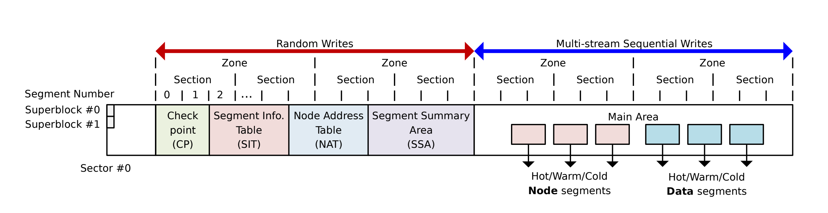
9.1.1. Sequential Write Area (Main Area)
This area is dedicated to log-structured writes of data, including file blocks and inodes. All writes are converted into sequential log entries. Segments within this area are categorized into:- Node Segments: Store inodes (aka "node blocks").
- Data Segments: Store file/directory data blocks.
9.1.2. Random Write Area (Metadata Area)
This area stores critical file system metadata at fixed logical addresses:- Superblock: Contains fundamental partitioning information.
- Checkpoint: Similar to LFS checkpoints, replicated twice, and stores the addresses of the Node Address Table (NAT) and Segment Information Table (SIT).
- Node Address Table (NAT): Similar to an inode map in LFS or the File Allocation Table in FAT, it locates all inodes (node blocks) in the main area.
- Segment Information Table (SIT): Analogous to the segment usage table in LFS, it tracks the number of valid blocks and a bitmap of valid blocks within the main area, facilitating segment cleaning.
- Segment Summary Area (SSA): It maps data blocks to inodes.
Also note that the NAT, SIT, and Checkpoint data are written to two distinct locations on the disk, providing redundancy. During checkpoint creation, the updated version is committed to disk. The SSA, written to a single location, can be reconstructed from other available information.
9.2. Reading a File
- The current directory's inode number is looked up in the NAT to obtain its on-disk address.
- The directory's inode is retrieved to find the location of its directory blocks.
- The directory blocks are read to locate the inode number of the target file or subdirectory.
- Steps 1-3 are repeated until the desired file's inode number is found.
- The file's inode number is looked up in the NAT to get its on-disk address.
- The file's inode is retrieved to determine the location of its data blocks.
- The file's data blocks are read.
9.3. Writing to a File
- The file's data to is written allocated file blocks (possibly new ones) is buffered.
- The file's inode is updated to reflect the updated block locations within the log. This updated inode is also buffered.
- If the file is new:
- The directory block is updated to include an entry for the new file and buffered.
- The directory's inode is updated to reflect the new directory block location and buffered.
- A journal entry is added to update the NAT and SIT and buffered.
- All buffered updates in step 1-3 are then written to segments. Data blocks go to data segments while node blocks go to node segments.
fsync
9.4. Inodes
An inode contains (shown in figure 2):
- File attributes and metadata, including the file name, inode number, size, and modification time (mtime).
- Direct pointers to the file's data blocks or, for small files, inline data.
- Indirect pointers, which point to blocks containing further pointers to the file's data blocks.

Problem: Wandering Tree Problem in LFS
The inode map in LFS only tracks the location of the inode itself, not its associated indirect blocks. The addresses of these indirect blocks are solely maintained within the inode.
This design introduces a critical challenge: when a new entry is added to an indirect block, the block must be written to the log, resulting in a change of its on-disk address. Consequently, the inode, which stores the indirect block's address, must also be updated and written to the log. Again, writing the inode to the log causes its own address to change, necessitating an update to the inode map. This, in turn, requires the inode map to be written to the log, creating a cascading update problem.
Solution: Inode Numbers for Indirect Blocks
In F2FS, indirect pointer blocks are also assigned inode numbers, requiring translation to physical addresses via the NAT.
The use of inode numbers for indirect blocks, registered within the NAT, addresses the wandering tree problem associated with LFS. When an entry is added to an indirect block, only the NAT needs to be updated; the inode itself remains unchanged.
9.5. Directory Structure
A 4 KB directory block (also known as a dentry block) is organized as follows:
- Bitmaps (27 bytes/216 bits): These bitmaps indicate the validity of each slot within the directory block.
- Dentries (216 slots x 11 bytes per slot): Each slot contains (shown in illustration 5):
- Hash value
- Inode number
- Name length and name
- Type (file or directory)
Illustration 5: Dentry structure.
- Overflow File Names (216 slots x 8 bytes per slot): This section accommodates file names that exceed the space allocated within the dentry itself.
These directory blocks are structured as a multi-level hash table, which exhibits O(N) worst-case complexity. In contrast, file systems like XFS employ B-tree structures, offering a more efficient O(log N) worst-case complexity.
9.6. Segment v/s Sections
10. Logging
10.1. Multi-head Logging
SSDs, unlike HDDs, eliminate the mechanical head, enabling parallel writes. Consequently, multiple segments can be written concurrently, with sequential writes occurring within each segment.
F2FS enhances data management by classifying segments into three categories: hot, warm, and cold, expanding upon LFS's two-category approach.
This classification impacts node and data blocks as follows:
- Node Blocks:
- Direct node blocks for directories are classified as hot.
- Direct node blocks for files are classified as warm.
- Indirect blocks are classified as cold.
- Data Blocks:
- Directory entry blocks are classified as hot.
- Newly created data blocks are classified as warm, analogous to the hot category in LFS.
- Data blocks moved during cleaning are classified as cold, analogous to the cold category in LFS.
The log, along with its corresponding segments, is partitioned into six distinct sections, each managing the log for one of the above categories. To maximize parallelism, F2FS maintains six open segments concurrently, one from each category (multi-head logging).
F2FS maps each of these six partitions to separate zones. While the paper lacks specific details, these zones likely correspond to distinct planes within the SSD. This zoning allows the log flash block to maintain set associativity, ensuring that its blocks map to a single zone.
10.2. Adaptive Logging
11. Cleaning
Section cleaning in F2FS is divided into foreground and background processes, each following these steps:
- Victim Selection:
- Foreground cleaning employs a greedy strategy, selecting the section with the fewest valid blocks. The number of valid blocks is obtained from the SIT.
- Background cleaning uses a cost-benefit curve, choosing sections based on the number of valid blocks and their age. This information also comes from the SIT.
- Valid Block Identification and Movement:
- The SIT is used to locate all valid blocks.
- The SSA is then utilized to identify valid node blocks associated with the data blocks. The SSA ensures that when a data block is cleaned, the corresponding node blocks are updated to reflect the data block's new location.
- The updated locations of the node blocks are buffered into the NAT and SIT journals.
- Lazy Migration: Flushing valid blocks doesn't immediately write to new sections. Instead, they are buffered into the page cache, organized into the disk pages of the new section, and marked as dirty. The operating system then flushes the entire new section to disk.
- Mark Victim as Pre-free:
- The victim section is not immediately freed. It is marked as pre-free and remains unavailable until a checkpoint is written.
- The checkpoint ensures that all updates to the NAT and SIT are committed (in order to honor fsync). Without this, the NAT and SIT might still reference outdated locations. Therefore, the section is only freed after the checkpoint completes.
12. Checkpointing and Recovery
It's crucial to reiterate that fsync only guarantees the persistence of data blocks and node blocks. Updates to the NAT and SIT are recorded as journal entries within a buffer, not written directly to disk.
A checkpoint operation then performs the following:
- All dirty node and dentry blocks residing in the page cache are flushed to disk. All dirty file data blocks are also flushed at this stage.
- Metadata modifications are temporarily suspended to ensure consistency.
- The NAT and SIT are written to dedicated, non-active regions on the disk. SSA is also written.
- The Checkpoint Pack (CP) region is written, containing:
- NAT and SIT bitmaps, along with any buffered journal entries.
- The location of the SSA blocks.
- Orphaned inodes: These represent inodes for files that were opened but not properly closed, requiring later garbage collection. This can occur, for example, when a file is opened by multiple processes and deleted by one before the others close it.
12.1. Roll-back Recovery
Roll-back recovery proceeds as follows:
- The most recent valid checkpoint region is located.
- The active NAT and SIT are retrieved from this checkpoint.
- Any journal entries are applied to the retrieved NAT and SIT.
- Orphaned inodes and their associated data blocks are deleted.
- A new checkpoint is created to finalize the recovery process.
12.2. Roll-forward Recovery
13. Evaluation
This study compares the performance of four file systems: F2FS, ext4 (journaling), BTRFS (journaling), and NILFS2 (LFS implementation), across mobile and server workloads.
Btrfs, a modern Linux file system, utilizes a Copy-on-Write (COW) mechanism, enhancing data integrity through snapshot capabilities.
TRIM, a command for SSD optimization, plays a role in the evaluation.
Mobile Systems:
- Inzone:
- F2FS outperformed EXT4 by 3.1x due to its ability to convert random writes to sequential writes.
- F2FS surpassed NILFS2 by avoiding synchronous NAT and SIT writes.
- Btrfs also outperformed EXT4 and NILFS2, leveraging sequential writes during COW, but it did not match F2FS's performance.
- Read and sequential write performance was consistent across all file systems.
- SQLite:
- F2FS excelled due to its log-structured nature, ideal for SQLite's sequential WAL log writes.
- Btrfs exhibited the poorest performance due to significant copy overhead.
Server Systems (SATA and PCIe):
- SATA:
- Sequential read/write performance was consistent (e.g., videoserver).
- EXT4's numerous small TRIM commands hindered performance, while F2FS's section-based cleanup was more efficient (fileserver).
- Log-structured file systems (F2FS, NILFS2) benefited varmail's frequent sync operations.
- PCIe:
- Performance mirrored SATA results, except in fileserver, where concurrent buffered writes normalized performance across file systems.
TRIM Behavior (Figure 5 Analysis):
- Figure 5 was hard to read due to the small plots, and magnified sections. It shows writes as blue crosses, reads as red circles, and discards as gray squares.
- F2FS and NILFS2 demonstrated increasing logical block addresses with each write.
- EXT4 and Btrfs exhibited higher TRIM command frequencies.
Multi-Head Logging (Figure 6 Analysis):
- With 6 heads, F2FS achieved a bimodal distribution in cleaning efficiency (note that Figure 6 is a cumulative distribution).
- F2FS requires at least 2 heads (data and nodes) and so 1-node analysis was not conducted.
Adaptive Logging:
- F2FS demonstrated superior random write performance at 94% device fill.
- F2FS's adaptive logging helped maintain performance parity with EXT4 at 100% device fill.
14. Paper Remarks
This paper highlights the power dynamic between hardware and software: hardware leads the innovation cycle, and software must adapt. The hardware trends will continue to dictate the direction of systems research, with quantum computing being the next major milestone for software architects.
Samsung’s vertical integration is a key takeaway; their deep understanding of SSD "nitty-gritty" allowed them to build a storage-aware file system that third-party developers might struggle to replicate. The paper is an easy, informative read and a great primer on SSDs.
Comments
Post a Comment